High-frequency longitudinally welded tubing (HF longitudinally welded tubes) have been used throughout a wide variety of engineering fields since the sixties. In the intervening years, it has also gained acceptance in applications that had previously been the province of seamless tubing for reasons of quality. One basic prerequisite for overcoming this barrier is clean, accurate removal of the inside burr. This is necessary for assuring that welding tubing is competitive with seamless tubing. Since around 1965, tubing manufacturers have employed a number of different proprietary designs to deburr HF-welded tubing. To date however, this has invariably involved major compromises in terms of both inside deburring tool handling, and attainable welding speeds. Ernst Blissenbach GmbH has more than 30 years‘ experience in the design, manufacture and installation of tube inside deburring systems. Throughout this time, the company has focused on meeting growing demand from the tubing industry. Blissenbach has done this by specializing in inside burr removal from HF longitudinally welded tubing.
Removing the inside welding burr is particularly critical in the manufacture of cylindrical tubing that incorporates a drawing operation to improve the form tolerances, with muffler tubes for the automobile industry as these are subjected to severe deformation. Reason: deburring helps reduce notching. As a consequence, formation of a correspondingly small, flat burr is critically important for keeping the cutting forces at the inside tube scarfer to an absolute minimum. Working in tandem with state-of-the-art high frequency generators, our impeder meets this requirement by delivering a high level of efficiency. The resulting improvement in service life figures in turn translates into cost savings achieved by significantly reducing downtime required for tool change. Moreover, high impeder efficiency paves the way for an increase in welding speed, which has a positive impact on the deburring process.
The importance of inside tube scarfing in the manufacture of high-frequency longitudinally welded tubing
To meet the stringent quality standards imposed by manufacturers of longitudinally welded tubing, our inside tube scarfer designs have to meet the minimal requirements listed below. Specifically, in addition to smooth, precision scarfing of welded tubing, this challenge calls for ensuring that:
- Spacing between attachment point and deburring point should be kept to a minimum in order to ensure maximum system stability.
- The mount should offer ease of vertical adjustment. In order to follow the weld radially, an orbital adjustment of the mount is likewise a practical feature.
- To prevent chatter marks on the inside surface of the tubing, the cutting ring must be pressed upward with a constant force.
- Cutting ring rate of cut should permit easy, reproducible in-place adjustment on the welding line.
- To permit speedy replacement, the cutting ring must offer ease of accessibility on the welding line while the production tube is open.
- Maximum cutting ring service life must be considered a given.
- Keeping chip length to a minimum must be the goal in order to ensure their easy removal from the production tube.
- In terms of production speed, using the impeder should produce no significant difference to working without inside deburring.
- The inside burr must be as small as possible.
Impeder Importance and Operation
Beside the tube forming the impeder is of particular importance when it comes to the shape and size of the inside welding burr. Experience has shown impeders with maximum ferrite volume in the impeder cross-section to produce superior results. Paired with state-of-the-art high-frequency generators, the result is higher welding speed, and consequently, a smaller inside burr formation.
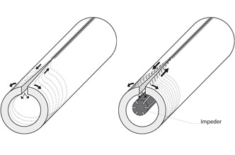
During high-frequency welding without an impeder, a current flows to the weld spot across the outside diameter of the tube. This fails to produce sufficient heating of the strip edges. Defective welds can be the consequence.
The field-conducting characteristics of the impeder concentrate the current along the strip edges of the slotted tube up to the weld spot. This boosts the component of usable welding performance, permitting an increase in welding speed of 20 to 60%, depending on impeder core material used [1]; [2].
To minimize current flow across the outside diameter of the tube, the impeder has to amply fill the inside of the tube. On the job, impeder diameter is determined by the work zone (inside tube diameter) of the inside tube scarfer attached to the impeder. In addition to impeder diameter, its length is also a major factor in reducing power input requirements, and consequently, in determining weld quality as well. Experience has shown longer impeders to perform better since they can significantly reduce the required power input for the tube welding line. The electromagnetic inductor field also extends upstream of the inductor, and induces a potential into the open slotted tube which drops with spacing. From that point, a current flows toward the weld spot. Lengthening the impeder produces improved conductance across the strip edges, even upstream of the inductor. This improves power feed. Industrial-use impeders are typically made up of individual ferrite rods. These rods are produced in certain lengths, e.g. 200 mm which permits the impeder manufacturer to group them by length. Field experience has demonstrated the benefits of the impeder extending from the weld spot past the leading edge of the inductor and twice the tube diameter into the slotted tube. When attaching an inside tube scarfer to the impeder, a number of requirements come into play concerning its strength. These are in addition to requirements governing its field-conducting characteristics. In previous impeder designs, the cutting forces produced during the deburring operation were absorbed by a load-bearing component in the form of an antimagnetic steel rod. With this approach, the ferrite cores are inserted into grooves milled into the load-bearing component distributed across its circumference.
Another configuration calls for a concentric arrangement of the ferrite cores around an antimagnetic, thick-walled tubular steel rod, where they are held in place by a guard tube.
However, these designs have an inherent drawback: they concentrate a high percentage of metal within the impedance zone of the inductor, thereby reducing its performance. The underlying cause for this are the eddy currents which, in turn, lead to a heating-up of the tension rod as well as a significant heating-up of the ferrite. For a temperature-sensitive material with a Curie temperature of 320°C, this is absolutely counter-productive and can cause failure of the ferrite itself! As a consequence, more recent impeder designs dissipate tensile force directly using the guard tube or a special tension rod material in order to avoid the effect described above. A special coupling system is used to provide improved coupling to the inside tube scarfer. This results in a magnetic flux comparable to tension rod designs.
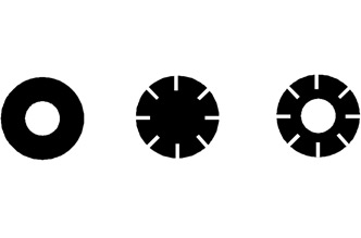
This has the effect of concentrating the lines of force more fully along the strip edges. The result: faster more directed heating. Dropping metal spatter, which the magnetic field inside the tube can quickly form into a metal lump, can damage the guard tube and thus destroy the core material. In a worst case situation, the inside tube scarfer connected to the impeder may be ripped off. To prevent this from happening, our impeder features a special coolant nozzle to prevent the emulsion jet from hitting the hot weld seam and causing welding problems. When working with very sensitive tube materials or very small diameters the use of backflow impeders, in which the coolant is returned to the mounting of the inside tube scarfer, is indispensable to avoid both welding problems and a reduction of the welding speed. When using backflow impeders it is important to make sure to use only a minimum of coolant in performing, as well as in the welding area, in order to fully benefit from the use of the backflow impeder. A common feature of all impeders is the use of a ferrite core material that is subject to strict requirements in terms of both permeability and magnetic flux density saturation. The high energy density in which the impeder operates produces a considerable amount of heat within the ferrite core, resulting from self-heating. This is caused by eddy currents propagated inside the core in a circular pattern near the surface. As a consequence, the use of cylindrical core materials has proven advantageous. These materials permit the current to increasingly spread along the longitudinal axis to provide additional cooling surfaces.
Although ferrites possess higher electrical resistance than metals, they conduct the current along the circumference. The more highly permeable magnesium zinc materials used in impeders feature a high degree of conductivity which produces eddy current heating. Supplemental heating by the inductor necessitates adequate, trouble-free ferrite cooling within the impeder. It should be noted that coolant supply must be operative before switching on the welding machine. Otherwise, the high starting current will destroy the ferrite material if not cooled.
The main contributing factor to impeder service life is structural fracture of the ferrite, resulting from mechanical influences through the production tube in case of misadjustment of the impeder, or caused by excessive heat exposure. Wear in the mechanical sense is not a factor. Broken ferrite cores in the impeder must be replaced without delay. This is because the resultant air gaps reduce the magnetic conductivity of the impeder. In turn, this results in loss of weld performance and quality.

